🌟 Trunnion Qualification Using NozzlePro
🎯 What is Trunnion Qualification?
In simple words, Trunnion Qualification is done to check whether the trunnion support welded to the pipe is strong enough to handle the loads without failure.
🤔 Why is it important?
If the trunnion fails, the pipe may bend, crack, or even break, leading to leakage or plant shutdown. So, we need to validate the strength of the trunnion and the weld joint to avoid failure.
🔥 How NozzlePro Helps in Trunnion Qualification?
NozzlePro is a powerful Finite Element Analysis (FEA) software used by Piping Stress Engineers to analyze localized stress in Trunnion, Branch Connections, and Nozzles.
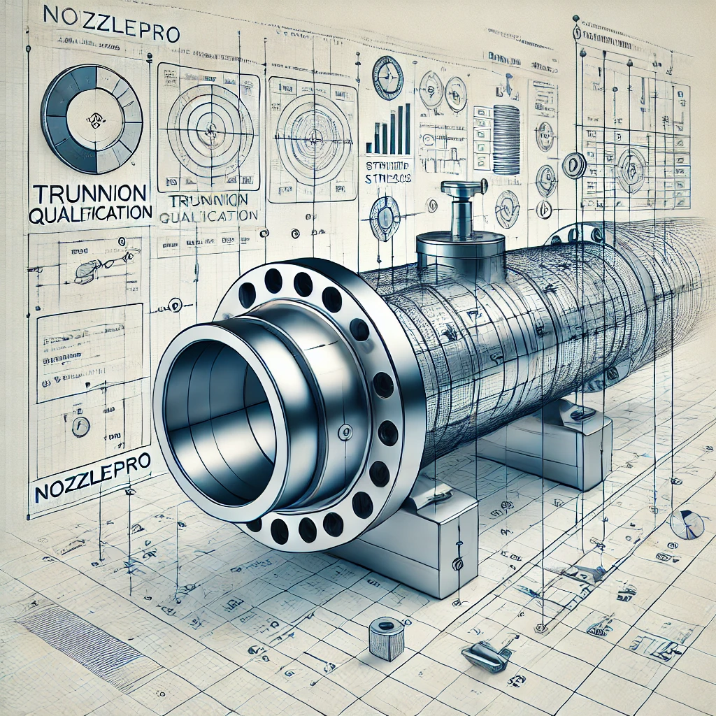
📍 Acceptance Criteria:
🎯 Final Output:
✅ Trunnion Strength OK
✅ Weld Strength OK
✅ No Risk of Failure
🌟 Why is NozzlePro Better for Trunnion Analysis?
- Provides Accurate Stress Results
- Considers Local Stress due to Welding
- Checks Stress Intensification Factors (SIF)
- Validates according to ASME B31.3 & ASME Section VIII Div. 2
🧐 What Happens if Trunnion Fails in NozzlePro?
- Increase Trunnion Thickness
- Increase Pipe Wall Thickness
- Increase Weld Size
- Use Reinforcement Pad
✅ Step-by-step process in NozzlePro for qualifying a structural member as a trunnion.


- Input all necessary parameters for shell.
- Wall thickness = corroded thickness
- Optional parameters not to be entered.

Select the appropriate nozzle or attachment type based on whether the trunnion is pipe-based or structural.

For structural-type trunnions, select the appropriate structural member from the drop-down menu.
- If the structural member is an angle, choose the correct ST member
by comparing the Sx (Elastic Section Modulus about the X-axis) and
Sy (Elastic Section Modulus about the Y-axis) from the AISC
Document.
- If the file does not run due to meshing issues between the pipe and
the structural member, reduce the width of the structural member
and note the change Technical notes.
- Input all required parameters for the nozzle or attachment type.
- Use the non-corroded thickness for wall thickness calculations.
- Nozzle length should be measured from the outside diameter (OD)
of the pipe. (The length shown on the isometric drawing is from the
center of the pipe.)
- Units: English.


Loads to be Applied at the End of Nozzle:
- For weight loads, use the maximum values from either operating or design sustained loads.
- For operating loads, apply the maximum values from either operating or design operating loads.
- For occasional loads, consider the maximum loads from specific occasional conditions like wind, seismic events, reaction forces, snow, etc.
- The nozzle and shell temperatures (inside/outside) should be the design temperature of the line.
- Design pressure and operating pressure should match the design and operating pressures of the line, respectively.


Select the nozzle and shell orientation vector based on the alignment of the pipe and trunnion axis.


Specify the weld size and pad weld size, typically found in the general notes of the support standard. If not provided, use the minimum wall thickness between the pipe and trunnion as the weld size.

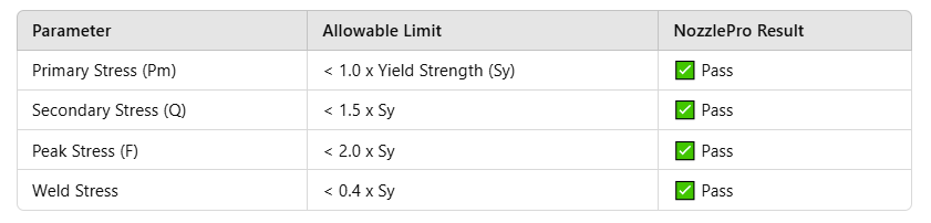
- In ASME Rules Options, ensure the ASME Section VIII, Division 2 Rule Set for 2013-2017 is selected.
- Make sure Include S1+S2+S3 for Code operating case is selected.
Ensure the "Do not cut hole in header for branch" option is selected.

- Select pipe and trunnion material as per the support standard (Refer to the notes of the support standard)
- For SA-36 material, choose based on product form (e.g., plates, bars, shapes, sheets - structural).
- Use ASME B31.3 for trunnion qualification.

Title:
