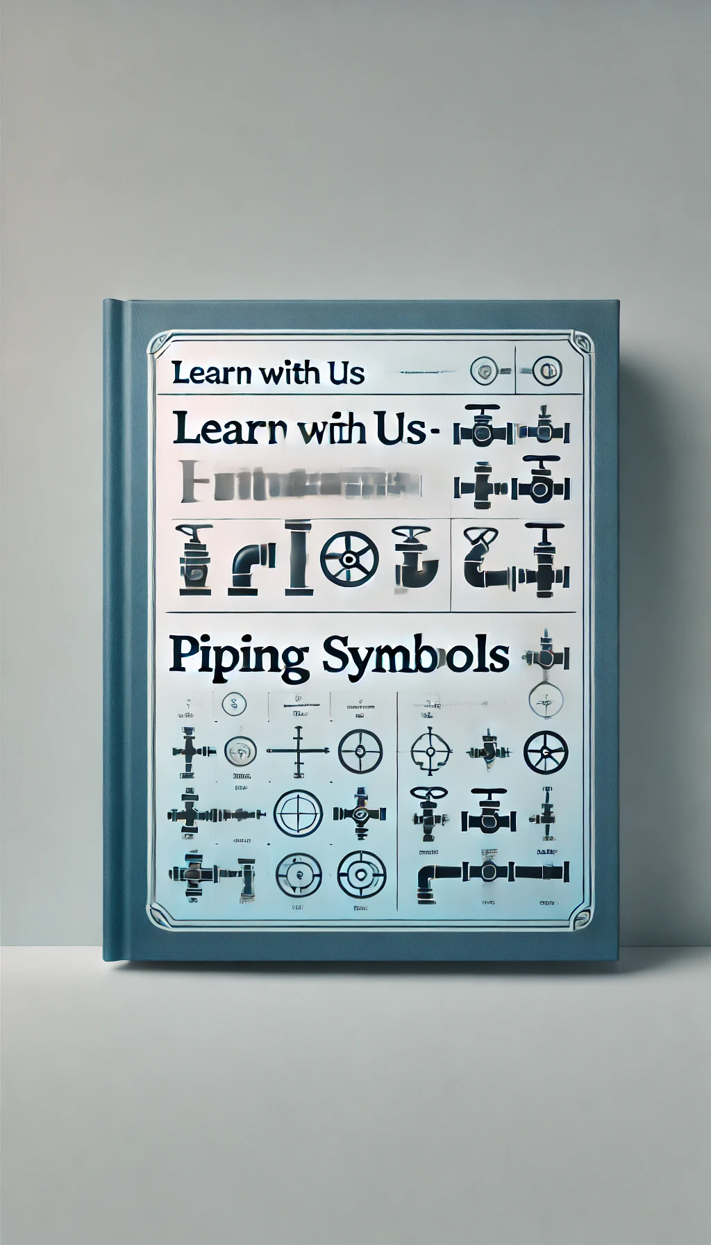
Understanding Piping Symbols in Drawings
Piping symbols are a standardized set of graphical representations used to depict piping components, systems, and layouts on engineering drawings. These symbols are essential for ensuring clarity and consistency, enabling engineers, fabricators, and installers to interpret and implement designs effectively.
Key Categories of Piping Symbols
Pipes
- Straight Pipe: Represented by a single line or two parallel lines (for larger pipes) in orthographic views.
- Elbows and Bends: Curved lines or symbols that indicate changes in direction, such as 90° or 45° bends.
Valves
- Valves control the flow of fluids in the piping system. Common symbols include:
- Gate Valve: A symbol with a line and a triangle or rectangle in the middle.
- Globe Valve: A globe or circular shape in the middle of the line.
- Check Valve: A line with an arrow or semi-circle indicating flow direction.
- Ball Valve: A filled or unfilled circle on the line, representing the ball mechanism.
- Valves control the flow of fluids in the piping system. Common symbols include:
Fittings
- Represent connections and junctions in pipelines:
- Tees: Lines meeting at 90°, forming a "T" shape.
- Crosses: Intersection of four lines.
- Reducers: A cone-like symbol, indicating a change in pipe diameter.
- Represent connections and junctions in pipelines:
Flanges
- Flanges, which are used to connect pipes, are depicted as circles or double circles on the pipeline.
Instrumentation Symbols
- Represent instruments used to monitor or control the system:
- Pressure Gauges: Circular dials or "PG" labels.
- Temperature Gauges: Similar to pressure gauges but marked with "TG."
- Flow Meters: Diamond shapes or arrows indicating flow direction.
- Represent instruments used to monitor or control the system:
Special Components
- Pumps: Represented by simplified shapes like rectangles with arrows for flow.
- Compressors: Circular or rectangular symbols with additional details to denote type (e.g., centrifugal or reciprocating).
- Heat Exchangers: Often represented with rectangles or a combination of circles and lines showing fluid paths.
Lines and Connections
- Solid Lines: Indicate process piping.
- Dashed Lines: Represent auxiliary or secondary piping.
- Double Lines: Show major pipes in orthographic views.
- Arrows: Indicate flow direction.
Standardization of Piping Symbols
Piping symbols are governed by standards such as:
- ASME (American Society of Mechanical Engineers)
- ISO (International Organization for Standardization)
- Indian Standards (e.g., IS 10714)
Adherence to these standards ensures uniformity in drawings, enabling professionals worldwide to collaborate effectively.
Importance of Piping Symbols
- Clarity: Simplifies complex systems for easier understanding.
- Communication: Acts as a common language among engineers, contractors, and fabricators.
- Efficiency: Reduces errors during design, fabrication, and installation.
- Documentation: Provides accurate records for maintenance and troubleshooting.
By mastering piping symbols, engineers can efficiently design, interpret, and implement piping systems, ensuring functionality and safety in industrial applications.


